
NSnappy Kide-LWEU
Introduction
NSnappy Kide-LWEU is a factory calibrated temperature transmitter with an IP67 protection class enclosure. Data is transmitted using standard LoRaWAN radio technology. LWEU-N models operate on the European license-free 868 MHz ISM radio frequency band. Kide transmitter can be mounted into a special smart Dock, which stores the configuration parameters for the transmitter. Once docked, the transmitter loads the configuration from the Dock. This enables an effortless calibration service and calibration replacements of Kide transmitters.
The transmitter is also available with a basic Dock which does not have the smart Dock features, but instead always uses the configuration parameters of the transmitter.
.png?inst-v=f839d60f-12d9-4ac9-a709-6cf21b6586c5)
Installation
NSnappy Kide-LWEU is ready to use when supplied from the factory. Upon shipping, it is automatically registered to the NSnappy service.
The transmitter and the dock are shipped with a default configuration and this configuration must match the configuration of the Hub or Receiver device receiving the data. See chapter Configuring the device later in this manual for more details.
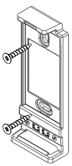
Install the Dock by following the steps below:
Choose the installation place so that it represents the measured conditions. Avoid heat sources.
Mount the Dock with two universal countersunk screws (ST 2.5 or ST 3.0). Use suitable length and type according to the wall material.
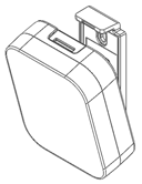
Attach the device into the dock observing its orientation. The metal inserts in the bottom of the enclosure must make contact to the spring clamp connectors in the Dock.
Power supply
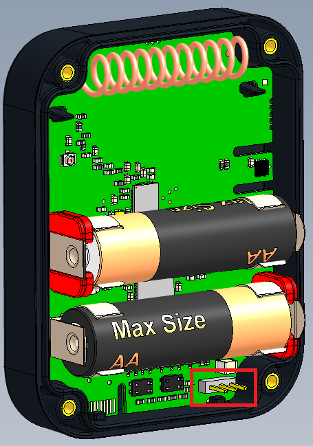
The transmitter is powered with two 1.5 V LR6 (AA) alkaline batteries. The device is supplied with batteries already installed, so it is ready to be used.
Connections
NSnappy Kide-LWEU uses the LoRaWAN wireless connection standard on the European 868 MHz radio frequency band to send the data to the cloud-based NSnappy service. There is a fixed radio antenna inside the enclosure of the device. Before using the 868 MHz radio, make sure it is legal in your country.
For the LoRaWAN radio reception to work, an NSnappy Hub 4G LWEU-N LoRaWAN gateway device needs to be installed on all sites where transmitters will be used. Please refer to the manual of the Hub device for its installation instructions.
There is a 3-pin connector on the circuit board inside the transmitter enclosure that can be used to configure the transmitter part. See the picture below for the location of this connector. Use a Nokeval DCS772 USB-POL converter and a POL-3PIN adapter to connect the Kide-LWEU to a computer to configure it with MekuWin software.
Configuring the device
There is usually no need to configure the device since most of the settings are already at their best defaults. However, if configuration changes are needed, the process varies between the models.
NSnappy Kide-LWEU is typically configured using the smart Dock. Once the device is docked, it loads the configuration from the Dock. Note that the loading of the configuration is not instantaneous. It is triggered by the outgoing radio transmission, so the current transmission period setting affects the configuration switch time. Please, contact the manufacturer to get a smart Dock setup with the desired configuration.
If a basic Dock (without a configuration chip and golden connections in the Dock) is used and the Kide-LWEU transmitter part needs to be configured manually, use the MekuWin program and a DCS772 (USB-POL converter). You can download the required MekuWin configuration program from Nokeval’s website for free. Follow these steps:
Remove the transmitter from the dock.
Open the enclosure by unscrewing the four Torx screws.
Connect a DCS772 with USB-POL-adapter into the 3-pin connector on the circuit board and the USB to a computer.
Launch the MekuWin program.
In MekuWin, select your DCS772 from the list and set the parameters as follows:
o Protocol = SCL
o Baud = 9600
o Address = 0
Click Direct.
A new window should open, showing the settings menus as a tree.
Conf menu
Period: Data transmission interval. Valid range 5min…120min (default 15min).
Ch2 response time: 90% response time of the synthetic response time temperature channel (aka slow response). Selectable to 30, 60, 120, 180, 240 or 300 minutes (default 60min).
The following settings should only changed if the device is not used with NSnappy service.
AppEUI: LoRaWAN application identifier.
OTAA: LoRaWAN activation mode. If not set, ABP is used instead. Selected mode affects the required security keys:
For OTAA: AppEUI + AppKey
For APB: Device address + AppSKey + NwkSKey
Quality: Select the reliability of the radio packet delivery:
Unconfirmed (default): The device will transmit each packet once not expecting any acknowledgement. If the packet is lost due to a collision with another transmission or any disturbance, it is lost.
Confirmed: After transmitting a packet, the device will listen for an acknowledgement from a receiver and retransmit up to two times if not getting acknowledged. If there is no acknowledgement, the device will discard the packet and decrease the number of retransmit for the next packet. If the device does not get acknowledgement, it will eventually send the packet just once. This setting increases the probability of successful delivery significantly but does not guarantee it.
Confirmed tx: This parameter controls the number of transmissions per packet if confirmed is selected as a transmission quality. Valid value between 1 and 8.
Port: The LoRaWAN specification provides a Port field. This can be used to distinguish different types of messages. Valid port numbers are between 1 and 223.
Max EIRP: This parameter controls the maximum transmission power of the device. Valid value between 0 and 14 dbm.
Datarate: This parameter controls the data rate of the modem. However, if the adaptive data rate is enabled, the MAC layer controls the data rate.
Adaptive datarate: Adaptive data rate enable. Two parameters affect the operation of the algorithm. Once the count of transmissions without acknowledgement reaches the limit, the server must acknowledge within the next N (num of ack delay) transmission. If there is no acknowledgement, the device tries to regain connectivity by lowering the data rate.
Operation
After the Kide device is successfully installed, it operates independently and automatically. The device sends temperature readings on two channels:
Ch1 – Temperature, fast response: Reading according to EN 13485 and EN 13486.
Ch2 – Temperature, slow response: Reading from Ch1 filtered with a user configurable low-pass filter. The low-pass filter enables more control over how quickly the device reacts to temperature changes and smoothes the temperature curve.
Both temperature readings are given in degrees Celsius.
Users of NSnappy can change the measurement unit in which temperature readings are shown, in their preferences.
Detailed data packet format is described for system integrators in the chapter Uplink payload structure.
Maintenance
Replacing the battery
Kide devices are powered with two 1.5 V LR6 (size AA) alkaline batteries. In order to replace the batteries:
Remove the device from the Dock.
Unscrew the four screws from the bottom of the enclosure and open the enclosure.
Replace the batteries with new ones observing the polarity.
Close the cover with the four screws making sure the rubber seal is properly seated.
Reattach the device into the Dock.
Cleaning
The enclosure can be wiped with a damp cloth moistened with soap water. We recommend the NHygiene fiber towels.
Avoid strong chemicals and never use abrasive substances or utensils for cleaning.
Service
The device does not require other regular service or maintenance.
NSure service and calibration subscription services are available for these device and these services include a periodic calibration and battery replacement.
Uplink payload structure
The following tables and examples describe how the data can be extracted from the uplink data packets' payload. This information is only needed when the Kide device is integrated into a system that is not provided by Nokeval.
The payload data format consists of a protocol version field and 1 or more messages in length-type-data format. Example payloads are presented at the end of this chapter for reference.
Size | Name | Meaning |
1B | Protocol version | Version=1 |
XB | 1 or more messages | See Message format |
Message format
Messages are presented in length-type-data format with optional age field.
Size | Name | Meaning | |
1B | Message length | Bits 0…6:
Bit 7: | Message length in bytes, excluding length field and optional age field. If 1, age field is included. |
(2B) | Optional age field | Age, uint16 * 60 seconds | |
1B | Message type | See Message type, e.g. 11 = Flagged utility | |
XB | Message data | Data, based on message type | |
Message types
Message types:
10 – Formatted measurement data
11 – Flagged utility
12 – Debug
14 – Dock identifier
The device may send other message types but those should be ignored. Start of next record can be found based on the length field at start of every message.
Type 10: Measurement data
Measured readings and status information about them.
Size | Name | Value/Meaning |
2B | Measurement format | Format, always 3 for the Kide devices |
XB | Data by format | See the table below |
Measurement data using bit flags to describe which measurement fields are included. If the device failed to measure a value, that field will be missing.
After the measurement flags, the measurement data is provided. Sometimes a conversion may be needed in order to get the reading right. All the needed conversions and the units they provide are described in the table below.
After the measurement data, the message has a status bit flags field describing which status fields are included, similarly to the measurement bit flags. Generally, if the device failed to produce a measurement, it will have a status code to help identify the issue.
Size | Name | Value/Meaning |
1B | Measurement flags | Tells which of the measurement fields are included. E.g. 0000 0011 = both readings 0000 0001 = Only fast response |
2B | 0 – Temperature, fast response | Conversion: int16 / 100 (oC) |
2B | 1 – Temperature, slow response | Conversion: int16 / 100 (oC) |
1B | Status flags | Tells which of the measurement status fields are included. |
1B | 0 – Temperature, fast response status | 0: Reserved for future use 1+: error number |
1B | 1 – Temperature, slow response status | 0: Reserved for future use 1+: error number |
Type 11: Utility
Utility data using bit flags to describe which fields are included in the message, similar to message type 10.
Size | Name | Meaning |
1B | Bit flags | 0x00: Request to send utility. Otherwise: Describes which fields are included in the message. E.g. 0100 0001 = device type + serial number |
3B | 0 – Device type | <0-16777215> Product number of the device. |
2B | 1 – Firmware ver | <major 0-255> <minor 0-255> |
3B | 2 – Firmware build | <0-16777215> Build number to identify FW version more precisely. |
3B | 3 – Firmware ID | <0-16777215> Firmware identifier, for use with firmware update. |
1B | 4 – Battery info | <number 0-255> Highest bit: Describes whether the device has auxiliary power. Other bits: 127 = no battery attached. 0-100 = main battery empty/full (1% resolution). 101-121 = reserve battery empty/full (5% resolution). 126 = battery can’t be measured. |
2B | 5 – Calibration date | <0-65535> As days after 1.1.2000; 65535 means unknown |
XB | 6 – Serial number | <symbol> *[1-20], 32-126: Ascii-symbols, 128-227: 2 numbers encoded: ”00”, ”01”, ”02”… ”99” |
Type 12: Debug information
Debug information message. These should be skipped when reading messages.
Type 14: Dock identifier
Information for identifying the dock and the docking status of the device.
Size | Name | Meaning |
1B | Status key | Describes the current docking status of the device 0x03 = Dock type mismatch 0x04 = Dock POL connected 0x05 = Dock disabled |
2B | Last docking | If status key = 0 (i.e. the device is successfully docked), last docking indicates the time that the device has been continuously docked into the same dock. Otherwise last docking indicates the time elapsed since the last successful docking, expressed in minutes (up to 45 days) |
XB | Dock SN | Serial number of last the dock the device was attached to: <symbol> *[1-20], |
Example uplinks
Here are some example uplinks to help clarify how the uplink payloads are structured.
Bytes are presented as hex values, numbers are LSBF. E.g. consecutive bytes 0x01 and 0x23 converted to uint16 equals 0x01 + 0x23*0x100.
Example – normal measurement data
Bytes (hex): 01 09 0A 03 00 03 3B 09 D3 08 00
Interpretation:
Bytes (hex) | Name | Meaning |
01 | Protocol version | Version = 1 |
09 | Message length | Length = 9, excluding length field. No age field. |
0A | Message type | Type 10 = Measurement data |
03 00 | Measurement format | Format 3 = Kide device |
03 | Measurement flags | 0x03 = 0000 0011, meaning both readings |
3B 09 | 0 – T, fast response | 2363 = 23.63 °C |
D3 08 | 1 – T, slow response | 2259 = 22.59 °C |
00 | Status flags | 0x00 = No errors |
Example – uplink containing 2 messages
If there are more than 1 message in an uplink, they are simply one after another.
Bytes (hex): 01 09 0A 03 00 03 5C 09 E1 08 00 0E 0B 73 73 83 01 00 01 4F FF FF 50 AB 9C B3
Interpretation:
Bytes (hex) | Name | Meaning |
01 | Protocol version | Version = 1 |
09 | Message length | Length = 9, excluding length field. No age field. |
0A | Message type | Type 10 = Measurement data |
03 00 | Measurement format | Format 3 = Kide device |
03 | Measurement flags | 0x03 = 0000 0011, meaning both readings |
5C 09 | 0 – T, fast response | 2396 = 23.96 °C |
E1 08 | 1 – T, slow response | 2273 = 22.73 °C |
00 | Status flags | 0x00 = No errors |
0E | Message length | Message length 14, excluding length field. No age field. |
0B | Message type | Type 11 = Utility |
73 | Bit flags | 0x73 = 0111 0011, fields 0,1,4, 5, 6 are included |
73 83 01 | 0 - Device type | Type = 99187 |
00 01 | 1 – Firmware ver | Version = v0.1 |
4F | 4 – Battery info | Battery = 79% |
FF FF | 5 – Calibration date | Date = Unknown |
50 AB 9C B3 | 6 – Serial number | Serial number = P432851 |
Specifications
Environment | |
|---|---|
Storage conditions | -40…+70°C, without batteries, non-condensing |
Operating conditions | -30...+60°C |
Protection class | IP67 |
Enclosure material | ABS+PC, black, withstands mild acidic and basic solutions |
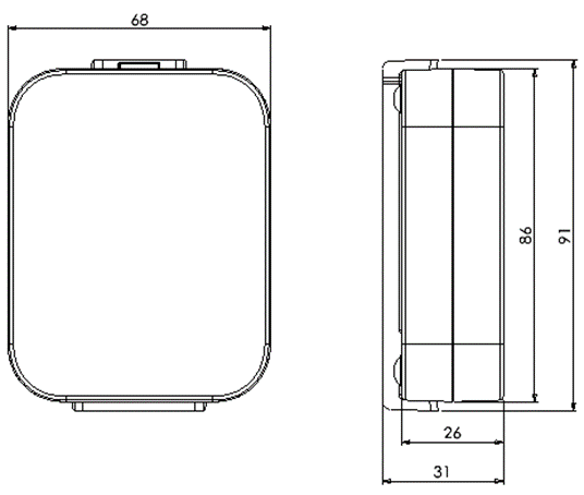
Dimensions | |
Dimensions | 91 x 68 x 31 mm, including Kide-Dock |
Weight | 136 g + 12 g Kide-Dock |
Temperature measurement | |
Sensor | Internal high-accuracy semiconductor temperature sensor |
Measuring range | -30…+60°C |
Accuracy | ±0.2°C (-30…+60°C) typical |
Measuring interval | 15 minutes, default setting. Configurable between 5 - 120 minutes. |
Response time | Channel 1: 15 minutes to 90% |
Radio connection (LWEU models) | |
Description | LoRaWAN standard, EU 868 MHz frequency range |
Transmitter module | Murata ABZ-093 LoRaWAN modem |
Antenna | Internal |
Compatibility | Nokeval NSnappy Hubs and Cloud Service |
Frequency | 863-870 MHz (LoRaWAN 1.0.2 EU band) |
Power | Max +14 dBm E.R.P. |
Range | Depends on environment, indoors: in good conditions up to hundreds of meters, outdoors: line-of-sight up to 10 km |
Radio connection (Sky models) | |
Description | Nokeval Sky radio technology |
Antenna | Internal |
Compatibility | Nokeval Sky radio receivers and gateways and NSnappy and Ovaport Cloud Services |
Frequency | Frequency band 433.05 - 434.79 MHz |
Power | Transmission power 10 mW E.R.P. max |
Range | Line-of-sight: Depends on installation location and environment, in good conditions 10 km |
Power supply | |
Type | 2 pcs LR6 (AA 1.5 V alkaline). For the best battery life, use high quality batteries. |
Battery life | 5 years minimum with 15 minute data transmission interval and default settings with good radio link |
Dimensional drawing
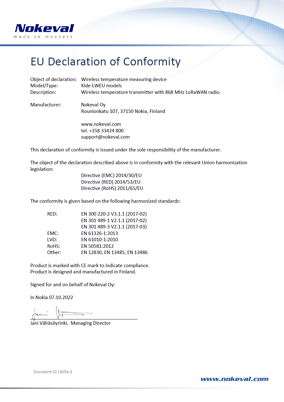
Declaration of Conformity
Warnings
This device contains a license-free ISM band (433.92 MHz) SRD radio transceiver. Observe local regulations concerning the use of such radio transmitters. Never start or use this device near explosion hazard areas or in areas where the use of radio transmitters has been limited, such as in airplanes, near medical instruments, near flammable liquids or chemicals or near explosion work sites.
Do not leave the product in direct sunlight or any other place, like in a parked car, where the temperature can rise to over +50°C. The battery may overheat and cause a fire or explosion hazard.
Read this manual carefully before using the product. Misuse may damage the product or cause other harm. Nokeval assumes no responsibility for any damages caused by inappropriate use or handling of the product.
Only Nokeval authorized services may repair or modify the product. The product contains no user serviceable parts.
The product must not be disposed of in household waste. Observe local regulations concerning the disposal of electrical waste. The device may contain a battery.
Trademarks
All trademarks mentioned and any logos reproduced in this documentation are the legal property of their respective owners. Nokeval and NSnappy are registered trademarks of Nokeval Oy.
Manufacturer
Nokeval Oy
Rounionkatu 107
FI-37150 Nokia, Finland
Phone: +358 3 342 4810
WWW: https://www.nokeval.com
Email: support@nokeval.com
Business ID: 2852422-8